Everything starts with the base.

A 127 millimeter square, 40 tall, with the lamp’s brain inside. Everything you put on top snaps on magnetically and is recognized on its own.

Back to how it works

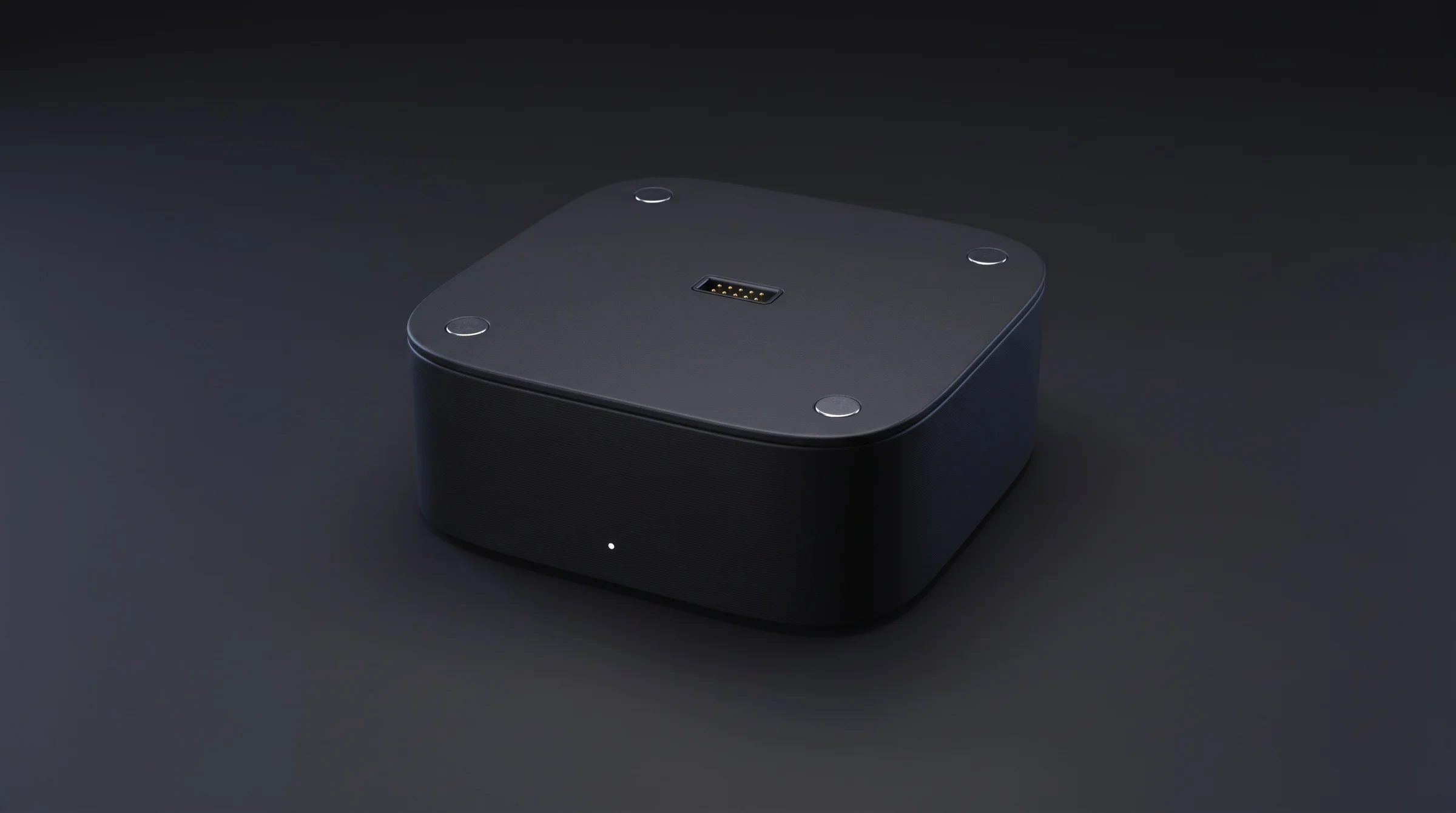
The STRAT base on its own, on a dark surface: a low box in matte black PLA, with four small magnets in the corners of the top face, the connector window in the center and a white status dot on the front.
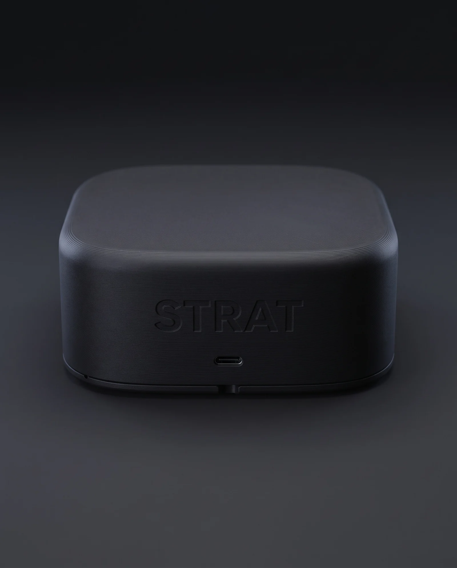
The back of the base, up close: the STRAT logo finely engraved in the matte PLA, the USB-C port below it and the notch in the bottom edge through which the cover opens.
The back of the base: the engraved logo, the USB-C port and the cover notch.

The brain sits at the bottom, where there’s room and it stays cool.

Inside the base sits a Raspberry Pi Pico 2 W, on the posts of the bottom cover. We chose it because it’s cheap, has Wi-Fi, is available everywhere and runs ESPHome, an open firmware you can read and change. Next to it, on a simple board, are the few parts a lamp needs: a 74AHCT125 level shifter that raises the data signal from 3.3 to 5 volts, a 330 ohm resistor on the data line, a 1000 microfarad capacitor that keeps the voltage steady when all the LEDs turn on at once, and a 3 amp resettable fuse.

The prototype is powered through a USB-C port at the back, at 5 volts, from any phone charger rated for at least 3 amps. The same voltage goes onto the bus, to the light slices, and to the Pico. It’s the simplest circuit that can work, and that’s exactly why we started with it.

For the product, we’re aiming for a 20 volt bus, negotiated over USB-C Power Delivery with an AP33772S controller, with a local 5 volt converter in each module. That way less current flows through the magnetic contacts, the tall slices are no longer at their limit and there’s room left for the charger on top. The slice’s frame and cover don’t change.
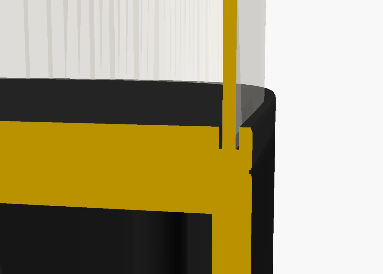
Cross section through the joint between the base and the light slice: the base wall, the slice frame and the diffuser, drawn in OpenSCAD.
Cross section through the joint: the edge of the base, the slice frame and the diffuser.

The base knows what you’ve put on it.

On the top face there are four 6 by 3 millimeter magnets, in the corners, and a 40 by 14 millimeter window in the center, for a magnetic connector with 8 pogo contacts. Two thick pins carry power and ground, and the other six are the signals: the data for the LEDs, chained from one module to the next, the I²C bus for the sensors, a select line and an interrupt that the sensor module pulls when it sees motion.

The magnets are glued in with north, north, south, south polarity. So a module sits in only one orientation, with the contacts where they belong, and it can’t be put on the wrong way round, even by mistake. The joint between the base and a slice is the same all the way around, a fine line between two edges rounded to 0.8 millimeters.

In the first version, the modules have no microcontroller of their own: the base recognizes them by the I²C addresses of the sensors and by the configured number of LEDs. In the second, each module gets a small CH32V003 and announces itself through the select chain, so that the stack describes itself, in whatever order you assemble it.

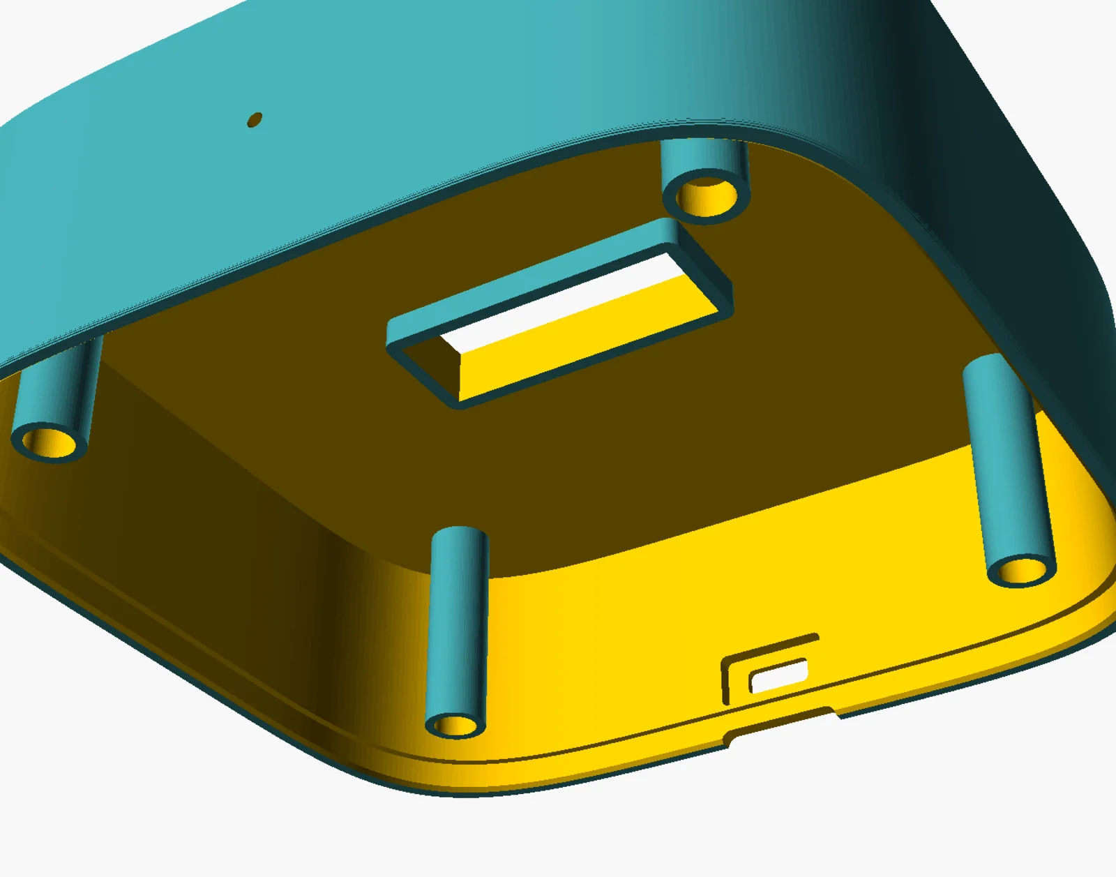
The base seen from below, in OpenSCAD: the cover pocket, the four bosses for the magnets, the stepped connector window and the notch at the back.
Underneath: the cover pocket, the magnet bosses and the connector window.

The bottom cover opens with a fingernail.

The base is printed with its top face on the plate, like a box with its opening facing up, in matte black PLA, with 0.12 millimeter layers, four walls and no supports at all. The holes for the USB-C port and the status LED, and the notch at the bottom, are small and print on their own. The edges are rounded in 0.2 millimeter layers, exactly the way the printer lays them down, so no steps show.

Underneath, the cover fits into a stepped pocket and is held by four magnets in bosses. Two 0.6 millimeter chamfers, one on the base and one on the cover, leave a fine, even line all the way around instead of a gap. The cover carries the posts for the Pico, so when you take it off, all the electronics come out with it.

To open it, you catch the edge of the cover with a fingernail through the notch at the back, under the USB-C port, and pull. No screwdriver, no clip to break. For the batch we sell, we’re also keeping a version with four countersunk M3 screws, for anyone who wants something firmer.

The lamp has its own page, on your network.

From day one, the base serves a web page on your local network. You open its address from your phone or laptop and there you have the light, the color, the sensors and the rules for the night. You don’t download any app, you don’t create any account and nothing leaves your home.

For anyone who already has a system, the lamp speaks the languages everyone uses: MQTT with auto-discovery and the native Home Assistant API. If you want Matter, it works through a bridge. The firmware is ESPHome, on the rp2 platform, so you can read it, modify it and reinstall it yourself.

On the front, a single 2 millimeter white dot tells you it’s on and connected. That’s all. The rest of the lamp is light.

Specifications.

Internal code B40. The dimensions are those of the v0 prototype and may change.

Dimensions
127 × 127 mm, corners with continuous curvature
Height
40 mm
Material
matte black PLA, 0.12 mm layers, no supports
Brain
Raspberry Pi Pico 2 W
Power
USB-C 5 V in the prototype; target 20 V USB-C PD, with local 5 V in each module
Connector
magnetic, 8 pogo contacts (2 power + 6 signals)
Magnets
4 × 6 × 3 mm, N-N-S-S, only one orientation
Cover
at the bottom, held by 4 magnets, opened through the notch at the back
Firmware
ESPHome, rp2 platform
Integrations
local web page, MQTT, Home Assistant API
Cloud
none
Status
v0 prototype, being printed